Apollo/Range Instrumentation Aircraft Support of Apollo 17
Michael Zeitfuss - ARIA Communications System Engineer - Pan American World Airways - Aerospace Services Division
The Plan
ARIA support of the NASA Apollo missions required the development of two different plans. One plan for the support of the trans-lunar injection burn (TLI) and a second plan for ARIA support of the spacecraft reentry when it returned to earth from the moon.
For the Air Force Eastern Test Range (AFETR) Test # 2475 was the ARIA support of the Apollo 17 launch and reentry coverages under Operations Directive (OD) 48000A. The launch window opened at 0153Z/7Dec1972 for a launch azimuth of 72 deg and closed 3+38 (hr-min) later at 0631Z for a launch azimuth of 100 deg. The TLI could occur on rev’s 1, 2, or 3 in the Atlantic sector.
Planning for TLI began with the arrival of the trajectory information in the form of magnetic tapes, the telemetry and voice relay coverage requirements, the launch date/time information, the launch azimuths limitations, if any, and finally the time/locations of TLI.
For the Apollo lunar missions, the combination of launch azimuth limits, earth parking orbit duration constraints, and the geometry of the moons orbit confine the location of the TLI positions to two geographical sectors. These areas were generally centered over the South Atlantic Ocean and the Pacific Ocean, and for this reason are distinguished by these names. The bounds, as illustrated in Figure 3, are defined by the first orbit for a 72° launch azimuth and the third orbit of a 108° launch azimuth.
Apollo 17 TLI was defined as an Atlantic TLI burn. From Figure 2 you can see that the coverage area extended from central Africa on the east to central Brazil on the west and from 30 deg N latitude to 30 deg S latitude. The total area is approximately 23 million sq miles.
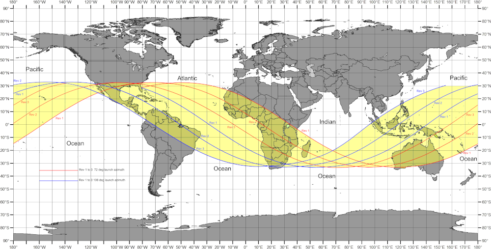
Figure 3: Apollo TLI locations for 72 deg launch azimuth and revolutions 1,2 &3 (red) and TLI locations for 108 deg launch azimuth for revolutions 1, 2, and 3 (blue). (NASA, Robin Wheeler)
ARIA coverage requirements for Apollo 17 TLI were from 60 seconds prior to TLI ignition to 60 seconds after SIV-B 2nd burn shut-down. The astronauts had a checklist that they went through after launch that nominally required an hour and 15 minutes to execute. Theoretically it was possible to complete on Rev Zero and have the TLI on Rev 1. However, the most probable TLI event would take place on Rev 2. A delay in readiness for TLI could also result in the TLI event taking place on Rev3. From an ARIA support perspective; these variables resulted in planning for Rev’s 1, 2, or 3 for the TLI event.
The planning process began with getting ground track computer printouts from the computer lab in Bldg 989, plotting the locations on a Mercator projection map (obtained from the map room located on the 2nd floor of hanger 800), and then determining possible staging bases, test support positions (TSP), and recovery bases that ARIA could use in order to be in the proper position for the required coverage over the full launch window. Ground tracks were plotted for every two degrees of launch azimuth and for Rev’s 1, 2, and 3. The process was iterative. Not all TSP’s were within the range capability of the ARIA and a different staging and recovery base had to be selected or a different TSP had to be selected or both. Further complicating the process was the need to obtain foreign over-flight and landing clearances through the Department of State. Eventually a set of: quantity of ARIA, their staging bases, their TSP’s, and recovery bases was obtained. For Apollo 17 five ARIA were required. Three would stage from Roberts Field in Liberia and two would stage from Ramey AFB, Puerto Rico. Roberts Field was selected because at the time of Apollo 17 Roberts Field had the longest runway (11,000 ft) in Western Africa. Recovery airports would depend on the launch azimuth, but would be somewhere in the Caribbean.
Once the Test Support Positions for the five ARIA were defined then look angle data sheets were created for each aircraft for each TSP for every two degrees of launch azimuth, and for Rev’s 1, 2 and 3. These look angle sheets of TSP (lat/long, altitude), time, and azimuth/elevation angle were assembled into almanacs for each ARIA. Each of the five aircraft’s almanac consisted of a set of 54 look angle sheets.
The next step in the planning process was to define the configuration of the ARIA for TLI support. During TLI the spacecraft transmitted telemetry data on six different link frequencies as shown in Table 1. The ARIA had 4 tracking receivers, 7 data receivers, two 14-track data recorders, and one 7-track voice recorder. Each receiver had to be configured with the: proper plug-in frequency tuning head, crystal, 2nd IF filter, Demodulator, and have various receiver front panel control switches specified.
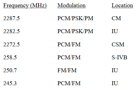
Table 1: Apollo 17 SIV-B & CM/SM Link Frequencies, Formats, and Locations
Each of the eleven receiver outputs had to be assigned to one of the two 14-track tape recorders. All of this data was given to the Prime Mission Electronic Equipment (PMEE) operators to properly configure the ARIA.
Once the TLI support plan was completed then the same set of variables went into the ARIA support plan for the lunar return reentry of the Command Module. The ARIA coverage requirements for reentry were telemetry and voice relay from: earth entry interface (defined by NASA as 400kft altitude) to entry blackout, exit blackout to CM splashdown, and continued
voice relay until release by NASA. The support plan for reentry was three of the five TLI ARIA would return to Patrick AFB and then redeploy to the Pacific to support reentry. One ARIA would stage from Hickam AFB, Honolulu, Hawaii and two ARIA would stage from Nandi International airport in the Fiji Islands.